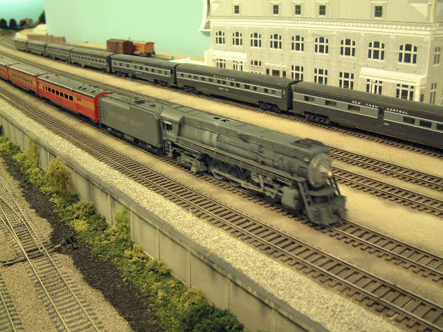
 With a total of over 26 scale miles of class A track, NA Prototype Modelers was an easy choice for our first feature club.
From time to time, we would like to bring you their story, in their own words. Our first feature club is North American Prototype Modelers based out of Milwaukee, WI and member Bob Peterson has shared a few thoughts about our tools.
 Its is impossible to not be impressed by the dedication that these professional men and women show to their club.
"I would like to extend a very big THANK YOU for making our lives a lot easier down at our Model Railroad Club N.A.P.M. (North American Prototype Modelers). Our club models in HO scale and occupies almost 6000 square feet of space for our layout. When the decision was made to build this layout, the electrical committee decided to install drops on every three foot section of flex track and every turnout in up to five locations. This decision has paid off now that the club has installed a D.C.C. system to control the locomotives and turnouts. The D.C.C. system requires perfect power distribution throughout the layout.
 In order to run on the NAPM layout, locomotives must be equipped with special digital decoders.
We set out to find a better solution and purchased an American Beauty resistance setup. We acquired your thermal stripper for smaller gauge wire, two single probe hand pieces, a ground wire and two sizes of tweezers. We then created a process that would allow us to finish a drop in the shortest amount of time as possible. Below is the process that we use and the pictures should make the phrase 'A picture is worth a thousand words hold true!'
 "When you have thousands upon thousands of solder joints to prepare...you don't want to use anything but the best...and easiest."
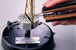
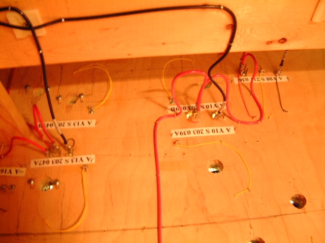
- The first step is to drill holes for the drop wires. Once this is completed we take a presoldered .250 male u shaped fast on connecter with a properly soldered color wire and route the wire from the underside of the layout. The U shaped fast on is screwed to the table at this time.
- Then we cut the wire to the proper length and then take the thermal tweezers and remove the insulation from the wire. We then proceed to shape the wire into a 'L' and align it to the side of the rail.
- Then with the use of either the smaller single node hand piece and a ground wire or the small tweezers, we then hold the wire in place to begin the soldering process. Once everything is in place, I activate my iron with the foot switch and count to one one thousand. By the time I have reached this far in my count, the solder has typically flowed into place making a perfect connection.
- I never have to worry about melting any ties as the heat remains isolated to the area that we are soldering. While soldering to turnouts, extra care must be taken not so melt the solder holding the throw rails together or causing the frog to become misaligned due to melting the plastic that holds the frog in place.
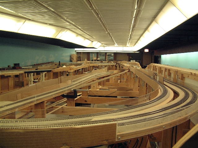 All the hard work and dedication has created an impressive layout that is routinely opened to the public schools for children of all ages to enjoy.
With your resistance iron, this is not an issue for us any more. We are also able to teach other members how to use the iron so that more hands on deck can assist us with getting drops in place. By practicing on a discarded piece of track, anyone can learn how to be a pro at soldering to our rails without melting any plastic ties or parts!
So we can only say THANK YOU for making a great product that saves us time and money."
Bob Peterson,
NAPM
Milwaukee, WI.
If you have a story to share with us and other modellers across the country, please contact us today....it could be your club being featured next month!
A Customer's Story: Scratch Building with the SuperCheif 250
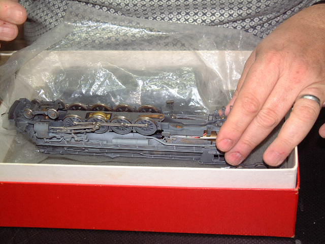
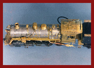
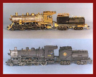 Back in 1986, I purchased a Bowser 2-8-0, HO scale, steam locomotive kit, a Pennsy H9. However, the model remained unassembled and the kit languished, for years, on the shelf. Time passed and in 1999 a magazine article was published that explained how to model a Central Vermont 2-8-0 in HO scale. The article was simply pure inspiration, giving construction guidelines and a list of commercial parts for superdetailing a 2-8-0 CV engine. Finally my H9 could be transformed into a workaholic looking steamer.
Reconstruction required removing the domes, cab, Belpaire firebox and many cast on details. These were to be replaced. As an "off-the-shelf" replacement cab was unavailable, a new one would have to be built from scratch. 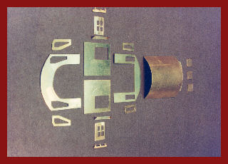
I had not worked that much with metals, let alone done any extensive soldering so I researched other magazine articles. I was actually able to locate the information needed to complete this project as one article provided component dimensions for the cab. It suggested that the cab be made from 0.010" brass which is very doable as brass easily worked and joined.
Once all of the detail parts were cut and filed, they needed to be joined to form the cab. For joining these components together I used lead free, silver bearing (95Sn5Ag) solder paste which has a higher melt temperature than the tin-lead solders most of us are used to working with.
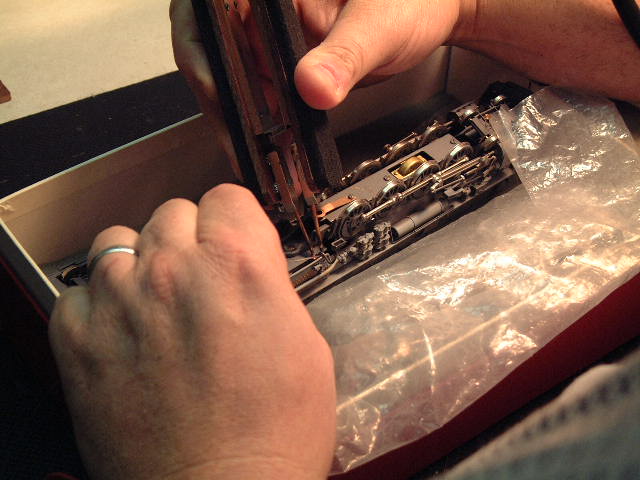
All of the soldering was completed using an American Beauty resistance soldering system, similar to the SuperCheif 250 and the Single Probe Accessory Kit. This system consists of a power unit, a tweezer style handpiece, a single electrode handpiece and current return lead, a footswitch and replacement electrodes.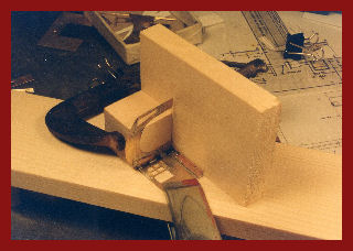
The single electrode handpiece was used in joining the cab walls. As an aside, it was necessary to extend the electrode as far forward in its holder as possible or about two inches. This additional length allows the electrode to get down into tight corners without interference from its holder. Needless to say it is required that the cab's corners are tight and square, so components were fixtured using milled one-inch blocks.
A thin bead of solder paste is spread along the inside of the joint to be. The tip of the electrode is then drawn along the bead causing it to melt and form a continuous, bright metallic fillet. This is repeated for the four walls and roof.
When using the single electrode handpiece you simply attach the clip of the return lead in close proximity to the intended joint, touch the electrode to the work and energize the footswitch. The electrode tip will instantly begin to heat up at the point of contact to melt and flow the solder. After the solder flows the footswitch is released but the electrode can be left in place to hold the components in position until the joint has cooled and the solder has hardened. This takes only a few seconds and assures a tight joint.
 The roof details are secured by laying them onto a small dot of solder paste and touching the electrode to the top of each detail to flow the solder. The smoke/wind deflector is attached by applying a dot of paste onto its back side. The electrode is touched to its front side and held until the solder melts and flows underneath wetting through to the front side forming a fillet along the back face between the roof and deflector. The cab awnings are attached the same way (apply the paste then resistance solder).
The cab for this project was soldered primarily with the single electrode handpiece, however the tweezer handpiece was also used for some of the work that was done.
When using the tweezer handpiece you simply hold the component between the tips of the electrodes, apply a little solder paste to the component and hold it in place. Depress the footswitch until the solder flows, then release the footswitch while still holding the component in place to cool.
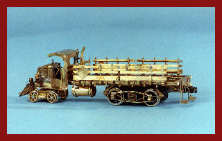 The cab for this railtruck was assembled using the single electrode handpiece in the same manner as the cab of the steam engine, but all of the flat details, side boards, etc. were joined together using the tweezer handpiece.
Honestly, I could not have built either the HO gauge steam engine or the 1923 Mack railtruck without the assistance of my American Beauty Resistance soldering system. It enabled me to make joints adjacent to each other that would have been impossible with a soldering iron or gun.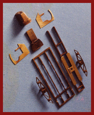
Story & photos submitted by Frank Hermanek - Lawrenceburg, Indiana.